STM32 Pocket Game / Dev Console is an early embedded hardware project where I was first introduced to battery-powered system design, LCD integration, and ARM-based microcontrollers.
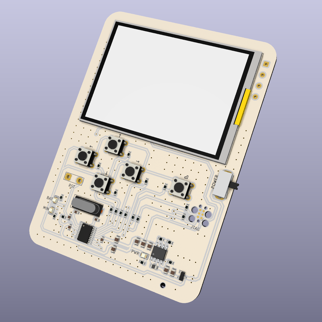
The goal was to design a compact handheld device that could function as a simple game console or development board, featuring a small display and a limited set of input buttons.
Inspiration
The project was inspired by a desire to recreate a very simple game experience — specifically Snake from the original Nokia 3310 — while learning embedded hardware design along the way.
Rather than emulating the game in software, the intent was to build the hardware first and adapt the firmware to the platform’s constraints.
During development, it became clear that the chosen microcontroller had limited memory resources, and storing graphical assets quickly exhausted available flash and RAM. As a result, the original game idea was postponed in favor of focusing on display control, input handling, and system bring-up.
Hardware design choices
The device is based on an STM32F-series microcontroller, selected primarily for:
- Low cost
- ARM Cortex-M architecture
- Access to professional tooling and documentation
This project marked my first use of SWD (SWDIO/SWCLK) for programming and debugging, as well as STM32 configuration tools.
Key hardware elements:
- STM32F-series MCU
- SPI-based LCD using a 4-wire interface
- Five input buttons, one of which doubles as a boot-mode selection pin
- Power supply based on 2×AAA batteries
- Boost converter to generate a stable 3.3 V rail
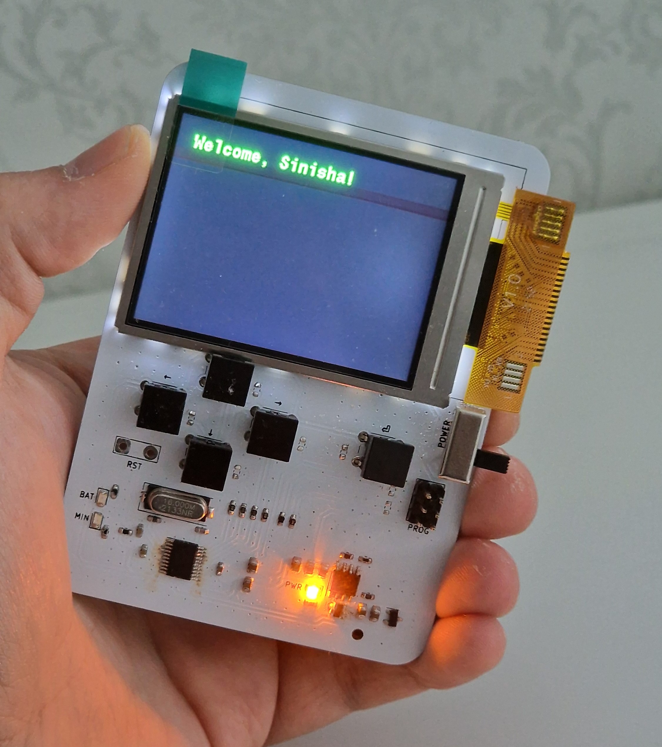
The LCD driver was available and functional, and SPI provided sufficient bandwidth for basic graphics and acceptable refresh rates given the hardware limits.
Power and battery considerations
This was my first battery-powered PCB, which introduced several new considerations:
- Voltage conversion from alkaline cells
- Stable operation across battery discharge levels
- Ensuring the MCU and LCD received a clean 3.3 V supply
Using a boost converter simplified the power architecture but required attention to component selection and layout to avoid instability under load.
Firmware integration
Firmware development was done using the official STM32 IDE and tooling.
This allowed:
- Clock configuration
- Peripheral setup (SPI, GPIO, ADC)
- Pin multiplexing
- Driver integration
While powerful, this toolchain was also more complex than what I had previously used, making this project an important step toward professional embedded workflows.
A limitation encountered was the use of graphics libraries that were not well-suited to the MCU’s memory constraints, which reinforced the importance of matching software architecture to hardware capabilities.
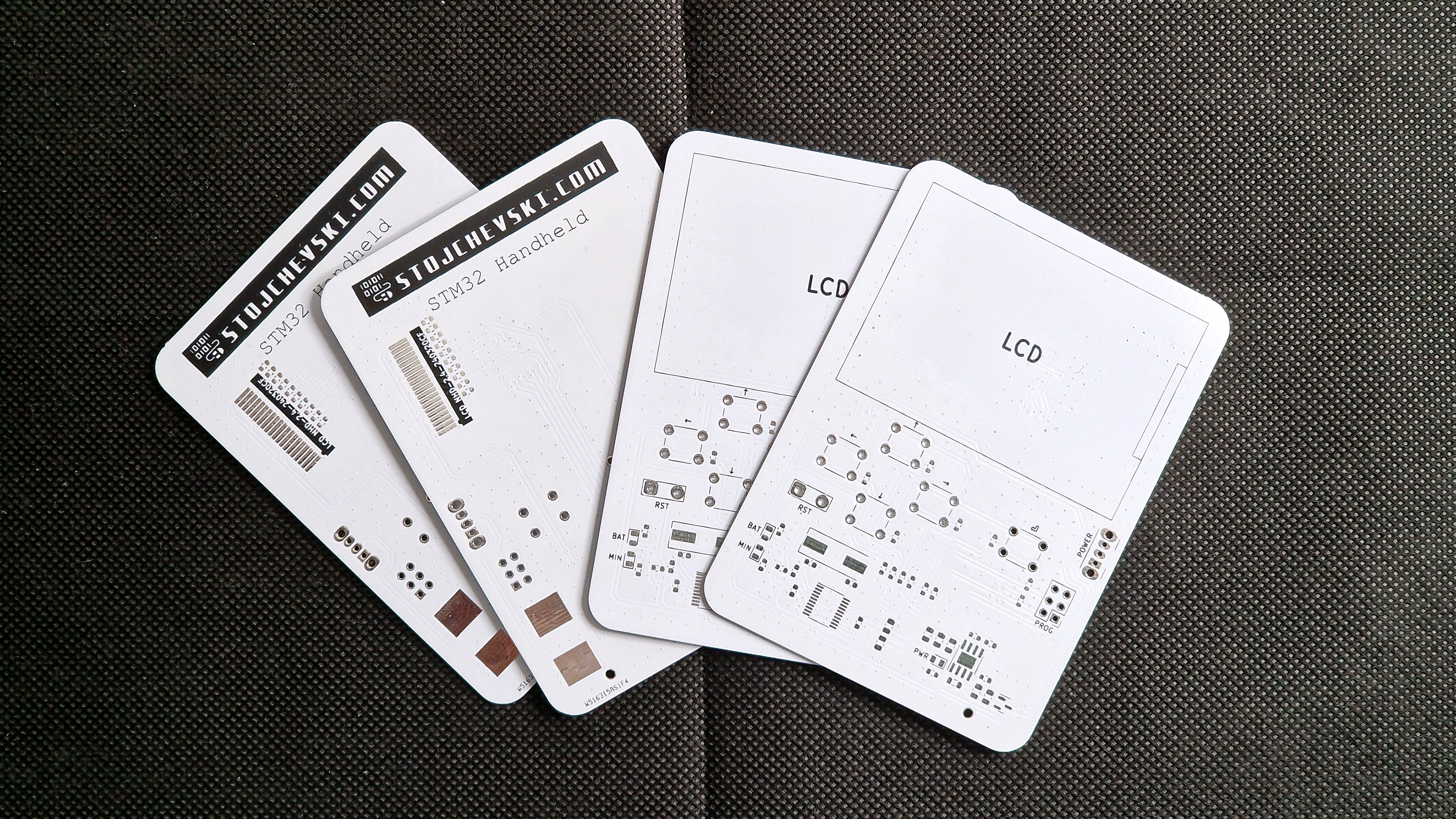
Manufacturing considerations
The PCB was manufactured and sponsored by PCBWay.
Assembly was done manually. During the first revision, an error in the schematic caused an ADC-related pin configuration issue, resulting in repeated pin failures during testing. This required manual desoldering and rework.
The issue was corrected in the second revision, reinforcing the importance of:
- Careful peripheral pin assignment
- Verifying analog signal paths
- Iterative prototyping
Open-source project
Both the hardware design files and firmware source code are available on my GitHub profile.
The project is shared as a learning reference and reflects an early stage of my embedded development experience.
Conclusion
This project was an important milestone in my transition from simple microcontroller projects to battery-powered embedded systems with displays.
Key lessons learned:
- Battery-powered designs introduce entirely new constraints
- LCDs quickly expose memory and bandwidth limitations
- ARM-based MCUs require more structured tooling and workflows
- Early schematic mistakes become very real during bring-up
Although simple in scope, this project provided foundational experience that directly influenced my later, more advanced embedded and PCB designs.